Problem Statement
Currently, the nose cone refurbishment tool is too manually intensive and prone to unnecessary errors. Our group is tasked with creating a new system that allows for there to be not only a safer but a more consistent and easier process for their refurbishment. Important aspects of this design are the load ring being inserted nose cone. Inside are many important components easily prone to damage. The lifting needs to be very precise and be able to hold 130lbs. Primary issues to highlight:
- Generate FEA simulations for design
- Determine lifting mechanism for load ring
- Create a strong contraption to support the nose cone
- Have a highly maneuverable design
- Be strong enough to handle consistent wear and tear of workshop life
Main Design Process
To begin this process, the first step is to ensure that our design meets each criterion that was set out by the above problem statements. To begin, we first went through several design changes. We went through several general design changes while continuously updating these designs. Below are a few of these designs.
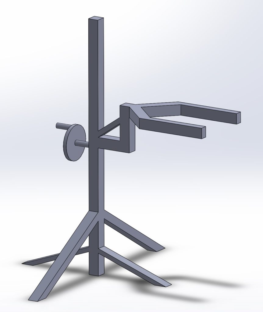
Figure 2: Mounted Design 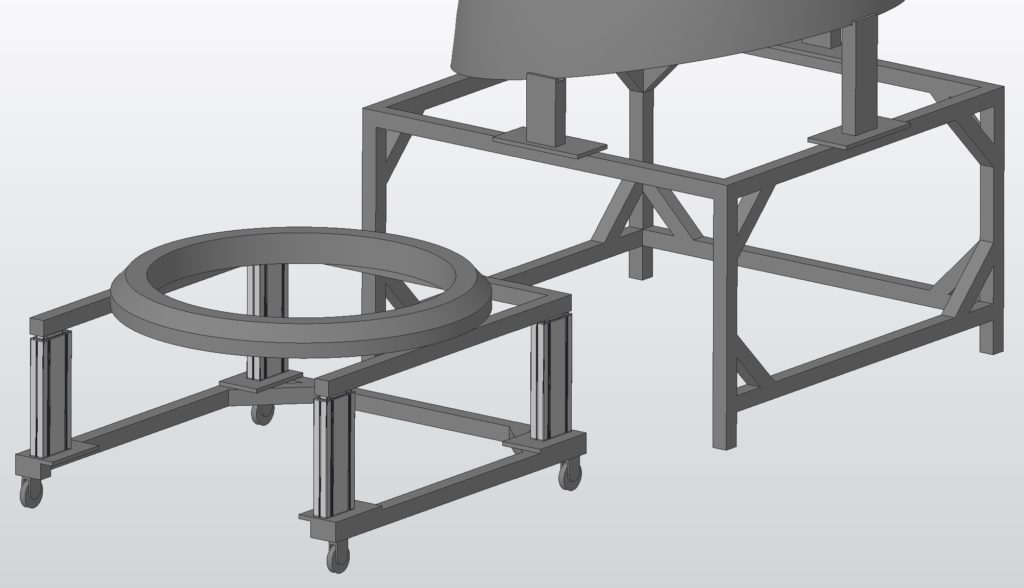
Figure 3: Initial Design 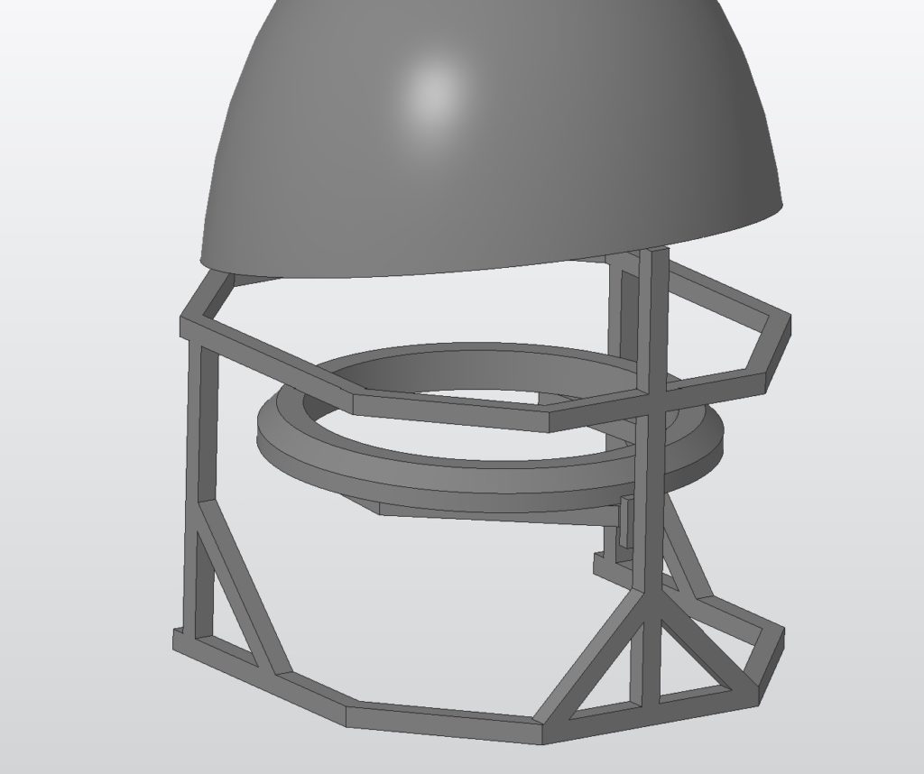
Figure 4: Self included assembly
Now each of these designs has merits. For instance, figures 2 and 4 are much smaller and take up less room on the assembly floor. However, they create many issues with ease of function and additional problems with accessing the load ring while it is under the nose cone. Upon further conversing with our sponsor, it was clear not only their ideal design was the one as displayed in figure 3 but also this design was the easiest to create and implement. After settling on the design, we went into further implementations to improve our design.
Materials
Materials are important for the design to ensure safety. With recommendations from teachers and our sponsor, we decided on Bosch tubing for the general design.
Further Improvements
One of the most important factors from our sponsor is easily the safety of the design. Our group decided to implement a safety mechanism to allow for this design to easily be moved and safely.
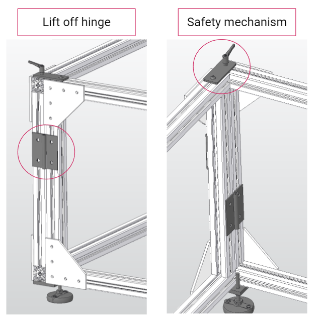
An important component of this design is the ability to move and properly store the entire design. The lift-off hinges and safety mechanism allow for easy removal.
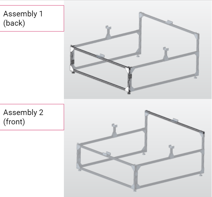
Figure 6: Front and Back Assemblies 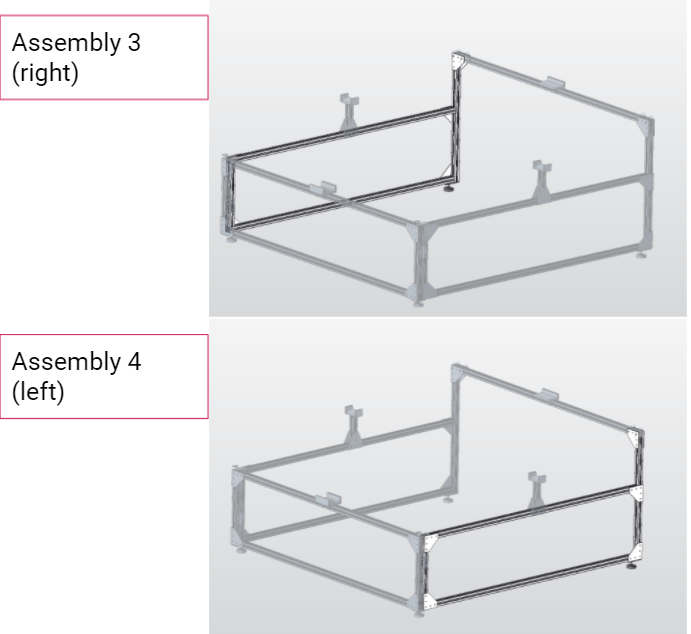
Figure 7: Left and Right Assemblies
The above shows how this component is split into multiple pieces. Each of the assemblies can be dismantled to create additional room on the assembly floor. These assemblies can be removed with respective lift-off hinges and safety pins which are documented in figure 8.

Once the design had been completed, to ensure the safety of each aspect of the design, it was imperative that there be FEA simulations completed. These simulations ensure that each component has at the bare minimum a FOS of 2 and that deflection is relatively low. Breakout analysis was conducted to demonstrate the areas of concern.
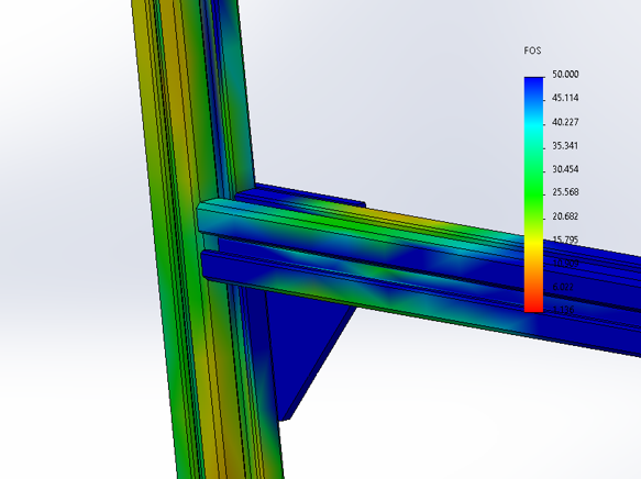
Figure 9: FEA of Joint 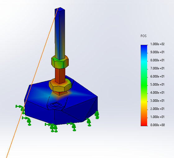
Figure 10: Max FOS is present on the legs of the system 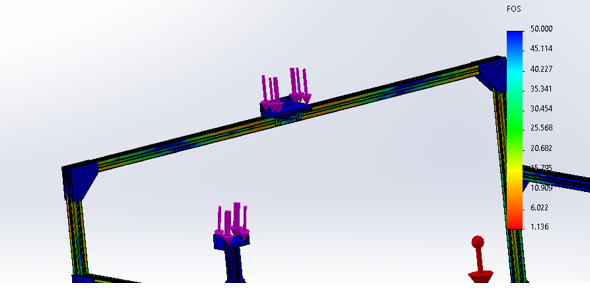
Figure 11: Overarching FEA simulation
Figures 9-11 represent a few screenshots of the FEA. Here it was important to determine where there are issues in the design that need to be replaced. We made sure that these legs can support this system. The lowest the legs reach on a FOS is 3.2 which is well within the range as prescribed by our sponsor and for general manufacturing design.
Cost
One of the most important components of this project is the cost breakdown. Due to a deal with the university, most of the products were able to be ordered from the same location. The cost breakdown includes unit price, quantity, vendor, catalog number, total price, and lead times.
Manufacturing Plan
Here our group realized quickly how important it was to create a plan to build and deliver this assembly. Our manufacturing plan began with a one-month schedule, and tasks were assigned to allow for us an easy way to go about creating this product.
Procurement Strategy
When considering lead times for the various manufactures, the products from Bosch and McMaster were negligible due to an agreement with the university which applies to rapid shipping. However, the lifting columns from Progressive Automation and the load ring from Tipke both took much longer to arrive. Lead times were an important component of the manufacturing plan, resulting in several aspects of our plan being readjusted depending on product arrival time.
Week 1
- Finish Ordering all parts (McMaster, Bosch, Progressive Automation, Tipke Manufacturing)
- Parts from Bosch over 80/20 due to tolerance issues (t-slots are not compatible for instance)
- Begin to manufacture the milling parts
- Begin working with our workshop to coordinate times and labor
- Organize inventory and being to delegate direct assignments
- Wait for lifting columns to arrive
Week 2
- Start cutting beams for the base of the nose cone platform and load ring cart
- Cut and drill all the brackets and hinges for ease moving forward
- Start assembling the nose cone platform
- Begin determining how to test for structural integrity
- Design and manufacture connection between lifting columns and bent ring
Week 3
- Start assembling the load ring cart
- Ensure Tipke manufacturing finishes assembly of the bent ring for the load ring
- Pick up the bent ring from Spokane
- Mill/Manufacture connection between bent ring and lifting column
- Install onto lifting columns
- Construct/Assemble the rest of the system
- Make an assembly guide and part catalog
- Test for structural integrity
- Testing the mobility solution with hinges, further improvement
Week 4
- Finish construction and testing of all assemblies
- Determine how to pack and ship individual pieces
- Accurately find each of the various shipping costs for each system
- Confirm shipping information and send our product
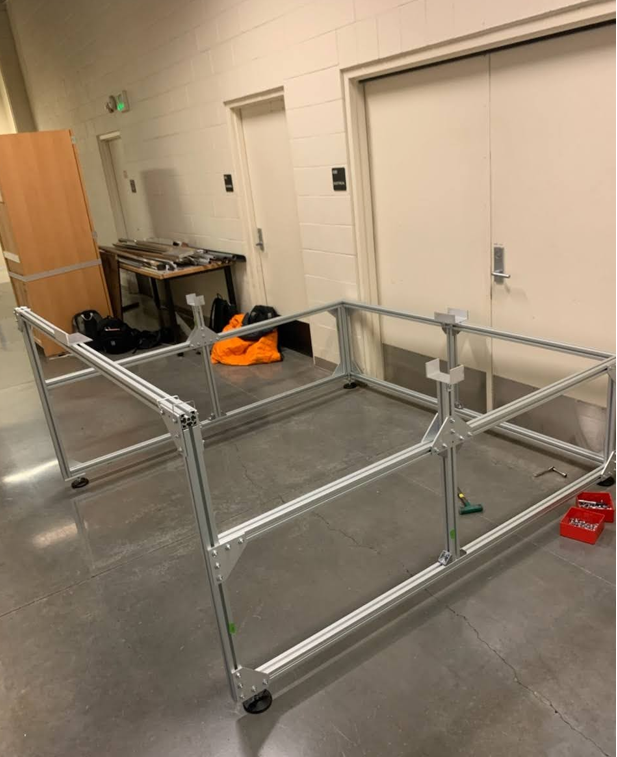
After the final construction of the product here is the final result:
Summary
This project is still being completed. Most of the aspects of the design were in the realm of our goals. Most if not all of the issues we ran into were relatively new experiences for us so I thought the best way to represent the project here is a list of the lessons learned.
Lessons Learned
- Learning how vital it is to have good communication with our sponsor.
Before, it was very common to not hear from our sponsor meaning we could not make consistent progress. So instead of relying on guesses, when we were able to communicate we both agreed upon a neutral time every week which worked incredibly well. With a project that relies on building a project from the ground up from a sponsor, this might be the most important step of this project.
- Understanding the importance of lead times and part list management
For this project, we ordered from 4 different manufactures. One important reason for this is some parts that McMaster had were not in tolerance for the Bosch beams we were using. So ordering from a variety of suppliers was a requirement. Tipke was commissioned to construct the load ring while progressive automation ordered the lifting columns. We commissioned the load ring to an outside manufacturer because our workshop did not have the capability of rolling steel. We realized that lead times for products such as these take much longer than initially expected. We realized how vital it was to be proactive with project components that are completely out of your control.
